Modifying the MSX character style
Knowing how to print characters on the screen using Assembly is nice, but creating your character style is the kind of thing that makes you feel awesome! At least this is how I felt after doing that, so let’s see if you also have the same satisfaction after this article.
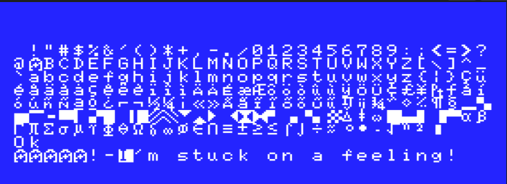
The MSX standard provides pre-defined 256 characters as explained on this MSX Resource center page, and we can notice that the character set changes depending on the region where the machine was developed. It’s also important to notice that all characters from 0 through 31 are control characters and cannot be printed on the screen and also cannot be redefined but from the character 32 (space) through 255 everything can be shown on the display. So why not start our work by printing all visible characters on the screen using both Screen 0 and 1?
; BIOS calls
CHGMOD:  equ 0x005f    ; BIOS call to change the screen mode defined at A
CHPUT:   equ 0x00a2    ; BIOS call to print a character at the screen
CHGET:   equ 0x009f    ; BIOS call to wait for a key to be pressed
; System variables
LINL40:  equ 0xF3AE    ; Width for SCREEN 0 (default 37)
LINL32:  equ 0xF3AF    ; Width for SCREEN 1 (default 29)
; Local custom values
COUNT:   equ 255-32    ; Defining the total value for the character count
CSTART:  equ 32        ; Defining the start of the character count


        org $D000      ; Our program will be stored at position $D000 in the memory

start:                 ; Program start
	ld hl,LINL40   ; Loads the system variable LINL40 address into HL
        ld (hl),40     ; then changes the value from the default 37 to 40
        ld a,0         ; We will load the value 0 into the Accumulator
        call CHGMOD    ; then we will call CHGMOD to change the video mode to screen 0 and width to 40
        ld b,COUNT     ; Let's create a counter by loading at register B the end value
        ld c,CSTART    ; and loading at register C the starting value
        call PrintLoop ; We can now call the routine PrintLoop to show the characters with values within our counter
        call CHGET     ; After printing the characer set, we wait for any key to be pressed before changing the screen mode again
        ld hl,LINL32   ; Loads the system variable LINL32 address into HL
        ld (hl),32     ; then changes the value from the default 29 to 32
        ld a,1         ; Load 1 into A
        call CHGMOD    ; then call CHGMOD to change the screen mode to 1 and screen width to 32
        ld b,COUNT     ; We set the counter again the same way we did before for screen 0
        ld c,CSTART    ;
        call PrintLoop ; then we call the routine PrintLoop again
        call CHGET     ; and wait for a key to be pressed
        ret            ; before returning to BASIC

PrintLoop:             ; Our usual routine to show characters at the screen
        LD a,c         ; We load the value from C into A, which corresponds to the current value of the counter
        call CHPUT     ; Send the character related to the value stored at A to the screen
        inc c          ; Increments the value at C
        djnz PrintLoop ; The djnz command decrements the value of B and compares to to 0, jumping to PrintLoop if the result is false
        ret            ; Returns to the part of the code that called the routine
        end start      ; Program end
The difference between this program and the one from the previous article is that we are printing every character based on the values from the counter defined as CSTARTCOUNT, instead of having a message stored previously. We have a new assembly instruction here — djnz — which is defined as the following:
Decreases B and jumps to a label if not zero. Note that DJNZ does a relative jump, so it can only jump between 128 bytes back/ahead.
There are other methods to create loops that can be more useful especially if we are dealing with 16-bit values, but we will discuss them in later articles. For now, we are happy to count from 0 to 255 and use djnz to jump to a nearby place in the code for our little character printing loop.
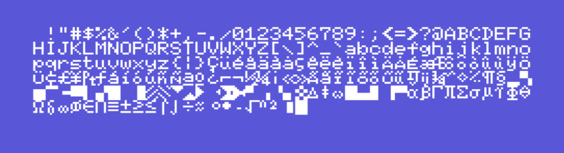
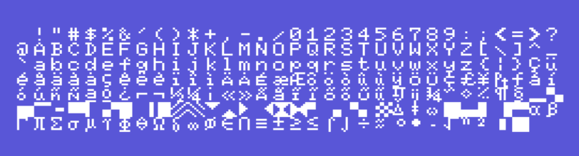
As I said in the previous article, the TMS9918 resolution is always fixed at 256×192 pixels independent of the screen mode used, so in order to fit 40 characters per line on Screen 0 (40×24 text mode) the system reduces the size of each character to 6×8 pixels, resulting in a total of 240 available pixels per line and discarding the remaining pixels. In terms of readability, it’s not totally bad, but for my new font type I choose to use Screen 1 (32×24 text mode) so I could use the entire 8×8 pixels available for my “art”. Another downside from Screen 0 is that we cannot change the font colors like Screen 1, although in the latter we can only change colors for an entire 8 character block, it’s still better than no option at all.
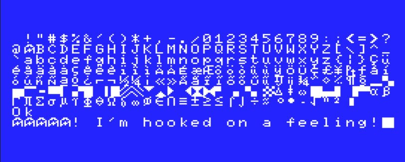
Oddly both screens 0 and 1 don’t start with the maximum width available for each of the modes, so we have to change the values from LINL40 and LINL32 system variables to fill the screen lines completely. Below are the default character sets available for a standard AMERICA/NTSC MSX system:
Can we start changing things now, please?
Sure we can! Let’s replace these boring type sets with something more interesting. But how do we do that?
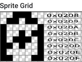
I’m not an artist at all, but I can try to do something different, and eventually, something interesting may come out. Knowing that the character pattern is a simple 8×8 pixels array and any tool that could give me the resulting in binary or hexadecimal from this could do the trick, I decide to use Jannone’s TinySprite tool for this work. Here is the design I created for the new letter A, fancy isn’t it?
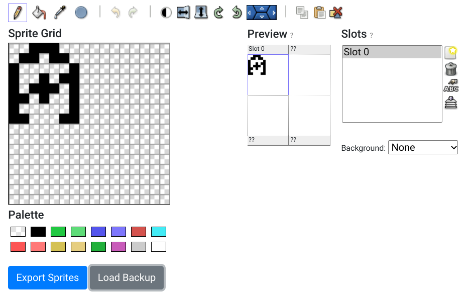
TinySprite was designed to work with 16×16 pixels sprites and is not the best tool to draw a single 8×8 pixels character pattern, but we just needed to ignore the additional DB lines filled with 0 values to end up with the desired output.
; --- Slot 0
; color 1
DB 00111000b
DB 01101100b
DB 10000010b
DB 10010110b
DB 10111010b
DB 11010010b
DB 10000010b
DB 11000110b
Now that we have the pattern for our new character A, we just need to put the information at the correct place in the VRAM and check the results:
; BIOS calls
CHGMOD:  equ 0x005f	; BIOS call to change the screen mode defined at A
WRTVRM:  equ 0x004d	; BIOS call to write the content from A at position HL in VRAM
CHPUT:   equ 0x00a2	; Imprime o conteudo de A na tela
; System variables
LINL32:  equ 0xF3AF	; Width for SCREEN 1 (default 29)

        org 0xC000	; ALocating the program at 0xC000 (slot 3)

start:
        ld hl,LINL32    ; Loads the system variable LINL32 address into HL
        ld (hl),32      ; then changes the value from the default 29 to 32
        ld a,1		; Load 1 into a
        call CHGMOD	; then call CHGMOD to change the screen mode to 1 and screen width to 32
        ld de,LetterA	; Loads the LetterA position into DE to be used at the loop
        ld hl,0x0208	; Loads into HL the VRAM position referring to the character A pattern
	ld b,8		; Let's create a counter to load all 8 bytes related to LetterA pattern into B
    	ld c,0		; and set into C the inital value for the counter, so it goes from 0 through 7

mainloop:
	ld a,(de)	; Loads into A the current value pointed by DE
	call WRTVRM	; Calls the BIOS routine that loads the value from A into the VRAM at the position HL
    	inc de		; Increments DE to fetch the next value from LetterA
        inc hl		; Increments HL to set the next position at the VRAM
	djnz mainloop	; The djnz command decrements the value of B and compares to to 0, jumping to PrintLoop if the result is false

        ld b,224	; Now we can create a new counter from 32 through 255
        ld c,32		; so we can once again print all visible characters at the Screen 1
        call PrintTypeset ; Calls our PRintTypeset to print all visible characters
        ret		; Return to BASIC

PrintTypeset:
        ld a,c		; Loads the value from C into A - from 32 through 255
        call CHPUT	; Prints the character related to the value loaded into A on the screen
        INC C		; Increments C for the next loop execution
        djnz PrintTypeset ; The djnz command decrements the value of B and compares to to 0, jumping to PrintLoop if the result is false
        ret		; REturn to the part of the code that called the PrintTypeset routine

LetterA:		; This is the pattern create for the letter A to be load on the  VRAM
        DB 00111000b    ; At screen1,the pattern table starts at 0x0000
        DB 01101100b    ; It's possible to use binary or hexadecimal values here
        DB 10000010b    ; but right now let's use binary since it's easy to manually
        DB 10010110b    ; change the character pattern
        DB 10111010b
        DB 11010010b
        DB 10000010b
        DB 11000110b
    	end start       ; Closes the program
The resulting program shows the new letter A on the screen. Can you spot it in less than 3 seconds?
The most interesting instruction here is the BIOS call WRTVRM, which is one of the methods available to transfer data from the value stored at register A into the VRAM at the position defined by the register HL. This call only moves a single 8-bit value per call, so it’s not the best option in case of having to move a longer block of data to the VRAM. I’m using this call in my example to make things simpler to understand and easy to demonstrate, but in the future, we will move to a more powerful call for the same action.
In Screen 1 (32×24 text mode) the Character Pattern Table occupies the VRAM from 0000H to 07FFH. I’m using the 0xnnnn notation so it translates to 0x0000 through 0x7000, but another possible notation for that would be $0000 through $7000, which we might start using in the future for better visualization.
Since the first visible character is the one with the value 32, and we know that each character is comprised of 8 lines of 8bits (or 8 bytes for short), we then multiply the first character value by 8 to have the VRAM position for the first printable character: 8 * 32 = 256, or 0x0100 in hexadecimal. Our target at this moment is actually the character for the letter A, which haves a value of 65, so we are looking to change the data at the VRAM position 65 * 8 = 520, or 0x0208 in hexadecimal
Now that we know the initial position at the VRAM for the letter A, we can use the WRTVRM call to write 8-bit values from 0x0208 through 0x020f and change the default pattern:
 ld de,LetterA	; The position for the 8 bytes of the new pattern - 00111000b
 ld hl,0x0208	; VRAM position of the first line of 8 bits for the letter A
 ld b,8		; Count to 8
 ld c,0		; from 0

mainloop:
 ld a,(de)	; Points A to the 1st byte stored at LetterA = "00111000b"
 call WRTVRM	; transfers 00111000b the position 0x0208 on the VRAM
 inc de		; Increments DE for the next byte - 01101100b
 inc hl		; Increments HL for the next position at the VRAM - 0x0209
 djnz mainloop	; decreases B and repeats loop if B!=0
; The loop ends when B decreases to 0, after the value 11000110b was
; transferred to the address 0x020F on the VRAM
What can we do more now?
You can try to change the pattern from the characters at the DB lines, and change the values from the characters to change other letters, or even try to change the blank space and see what happens on the screen! If anything breaks, running the command screen 0 fixes any issues.
Next article I will provide a completely new character set, and we will also change the colors of the font. See you soon!
Knowing how to print characters on the screen using Assembly is nice, but creating your character style is the kind of thing that makes you feel awesome! At least this is how I felt after doing that, so let’s see if you also have the same satisfaction after this article. The MSX standard provides pre-defined…
Matheus, a bit late for the comment for the post from 2021 year, but… this text mode (screen 1) and your code shows only 7 lines on the screen from 8 lines of data per char. Notice the bottom of the redefined A lettershape. But in the post with changing whole character set it seems to work.
https://www.oddbitmachine.net/en/2022/01/26/show-your-custom-font-on-the-msx-screen/
You are right, and I completely missed that. The values loaded into b at line 17 should be 8, and not 7 because we are missing the last WRTVRM call on the djnz loop. To fix that we either need to add steps before the loop or change b to 8, which will make the inc de and inc hl calls useless in the last iteration.
We don’t have the same issue in the other code because we use LDIRVM, which copies the whole block of data between the RAM and VRAM, and doesn’t relies on the dnjz loop.
Good catch, thanks for the heads-up! I already updated the text and the MSXPen code with the fix.